Connecting the Radio
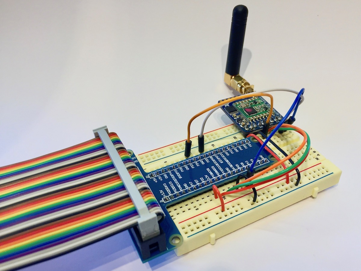
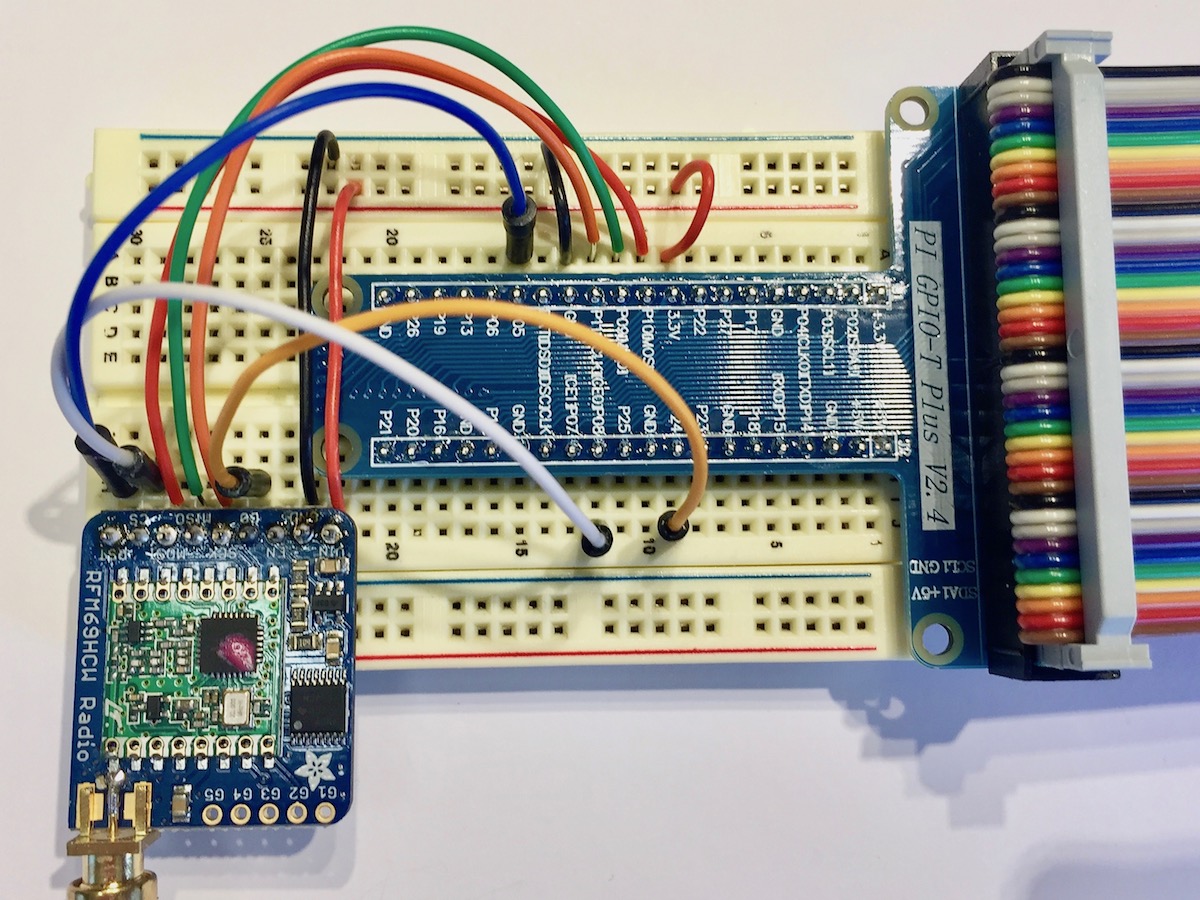
Wiring
The pins of the Raspberry Pi can be confusing and figuring out which pin is the right one and which one is going to make a loud popping noise can often mean repeated counting. If you struggle like I do, to mentally map from diagrams to the real world then I suggest buying or downloading a template card (a.k.a. a leaf).
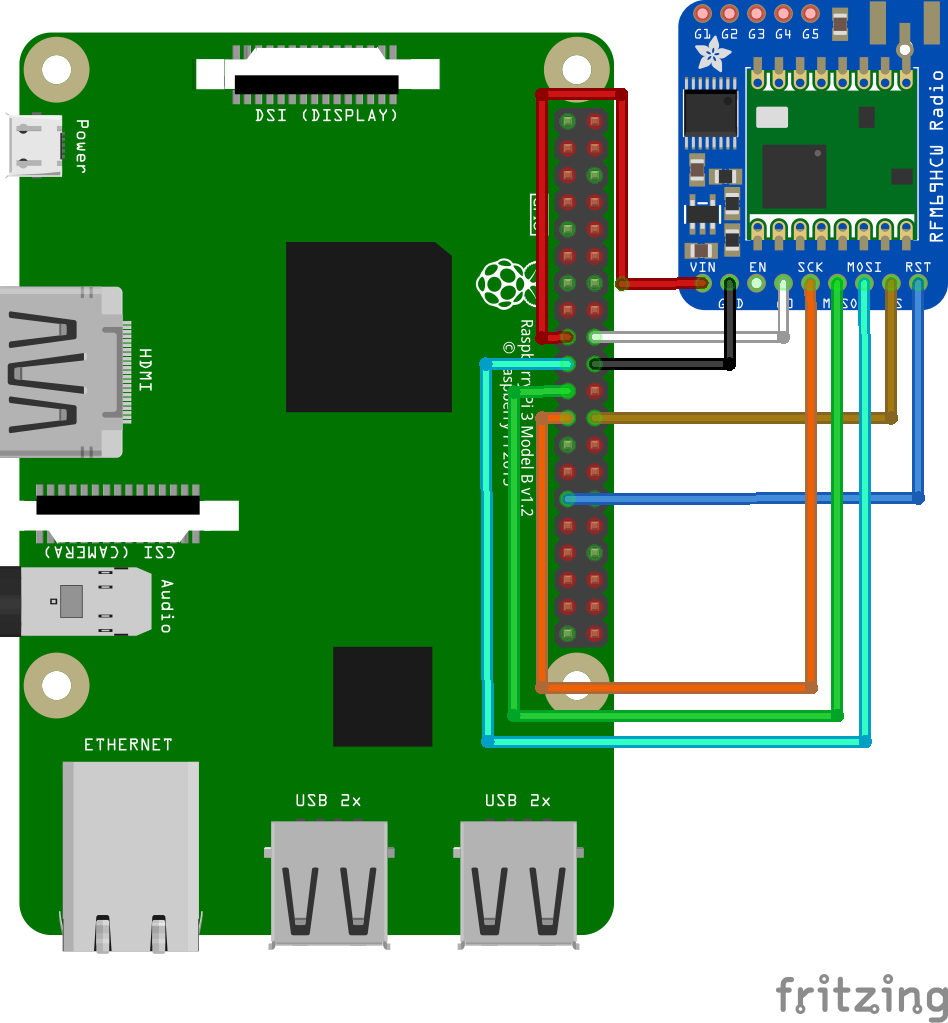
So that is how we are going to connect it all up. Different makes of breakout board use different terminology. For example the Sparkfun boards use NSS rather than CS and DIO0 instead of G0. The table below is my best effort at making the wiring clear. If you come across any different terms then let me know and I will include them.
Pinout guide
PI Name |
3v3 [1] |
Ground |
MOSI |
MISO |
SCLK |
ID_SC [2] |
CE0 |
|
PI GPIO [3] |
10 |
9 |
11 |
8 |
5 |
|||
PI Pin |
17 |
20 |
19 |
21 |
23 |
18 |
24 |
29 |
Adafruit |
Vin |
GND |
MOSI |
MISO |
CLK |
G0 |
CS |
RST |
Sparkfun |
3.3v |
GND |
MOSI |
MISO |
SCK |
DIO0 |
NSS |
RESET |
Footnotes
Setup Examples